Required Items
- IBM parts
| P/N 60G2258 |
Power
Switch/Cable |
$6.05 |
| P/N 13H8078 |
Dual LED
Indicator/Cable |
$2.25 |
These parts can be ordered via ShopIBM online at
http://commerce.www.ibm.com/
(just type the above part numbers under
"Know the part number?" and Click GO) or
in the US call
1-888-411-1WEB
- Aftermarket Parts
| (1) Floppy diskette
drive |
| (1) Floppy drive controller
cable |
| (1) IDE cable with 3
connectors |
| (1) ATAPI CD audio
cable |
| (1) Momentary push
button |
As far as the last item the mechanical switch that comes with IBM
kit P/N 60G2258
is really not desirable but that kit is required for
the OEM style cable and motherboard
connector. Pick up the smallest
momentary push button in stock at your local Radio
Shack or similar
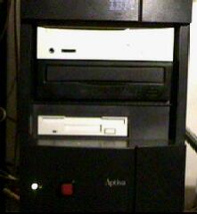
(see the red button with black border in the pictures below)
- Diagrams
Print out the following
documents:
Dumping the Media Console
- Unplug the system and disconnect the media console. Open the media
console and
remove the CD-ROM drive. Make sure to hang on to the
CD-ROM mounting screws
as you will need these to mount the CD-ROM in
your tower
- Open your tower and remove the power cable from the host adapter
card which the
media console plugs into. Remove the small cable
running between the motherboard
and the host adapter card.
- Remove the host adapter card itself. Cover the opening with a blank
insert if you have
one (such inserts can generally be found at PC
supply outlets).
- A few inches below the power supply on the inside rear surface of
the tower note the
small black box. This is the audio jack for the
media console. Externally this is where
the cable with the green
colored tip connects from the media console. Internally there
is a
cable running from this box to your Mwave card. Remove that cable from
the
connector on the Mwave card. If you wish (this is optional) can
remove the audio jack
itself by twisting it to the left which will
loosen the lock nut holding it to the case.
- Mount your original CD-ROM and new floppy disk drives in their
respective bays in the
tower. Verify that the jumper setting on the
CD-ROM drive is in the MASTER position
prior to mounting. I recommend
placing the CD-ROM drive right above the floppy drive.
Remove the
appropriate knock-outs from the case.
- Insert power cables into both the CD-ROM and floppy drives.
- Insert an IDE cable for the CD-ROM drive into the secondary IDE
controller socket on
the motherboard (J6). Place the other end of the
IDE cable into the CD-ROM drive.
- Insert an ATAPI CD audio cable into the rear of the CD-ROM drive and
then place the
other end of the cable into the CD audio IN connector
on the Mwave card (this is the
connector discussed in step 4 above)
or replacement sound card.
- Insert your floppy controller cable into the floppy controller
socket on the motherboard
(J21). Place the other end of the floppy
controller cable into the diskette drive making
sure that the
twisting section is between the drive and the motherboard. In a
system
configuration where TWO diskette drives (A: and B:) are to be
used one would connect
the un-twisted section of the cable into your
B: drive and then continue on to Drive A:.
- Remove the mechanical switch from the wires and connector on IBM P/N
60G2258
(power switch and cable). Just simply cut the wires at the
switch leaving as much wire
intact as possible.
- Strip the wires from IBM P/N 60G2258 and and solder them to the
momentary push
button, one wire to each prong of the push button. It
doesn't matter which wires you
connect to which prong as long as the
wires doesn't make contact with each other. I
highly recommend using
electrical tape to cover the bare metal parts of the button so
that
they don't make contact with the chassis.
- The mounting of the momentary push button is totally a matter of
user preference. I
chose to mount my button on the front of the tower
however if preferred one can mount
the button in the rear of the
tower through one of the knock-outs. Make sure that you
have enough
space between the plastic case and metal chassis to accommodate
for
the length of the button. If you mount the button on the front of
the case add an extra
length of wire so that you can slide the case
1/4 of the way off and unplug the connector
from the motherboard to
ease removal of the cover in the future.
- After the switch is mounted insert the connector into the 2-pin
power supply socket on
the motherboard (J23).
- As far as the optional LEDs IBM P/N 13H8078) I've mounted mine on
the front along
with the button. I used a 11/64 drill bit to make the
holes then used a small circular file
to clean up the rough edges.
I'd recommend using a smaller drill bit then working up to
11/64,
inserting the LED into the hole after each bit to insure a snug fit. I
don't suggest
using any type of glue or cement to keep the LEDs in
place as one cannot get to the
LED connector to unplug it once the
case is on metal chassis.
NOTE: Remember that the 3.5"
non-accessible drive bay below the floppy drive can be
used to
install an extra hard drive, keep this mind when choosing a location for
your LEDs.
- Place the connector of IBM P/N 13H8078 (LED assembly) into HDD/Power
LED socket
on motherboard (J26), then insert the LEDs through the
metal chassis.
- Slide the case 3/4 of the way on, once there you can push the LEDs
into their holes.
- Slide case the rest of the way on taking care not to pinch any of
the wires. Replace the
case mounting screws.
- Reconnect your monitor, telephone, microphone, speaker, keyboard ,
mouse and other
cables. Reconnect the power cord and plug the system
in.
- Push the On/Off button to powerup the system.
- The IBM BIOS should detect the change in CD-ROM drive
configuration...enter your
Setup utility and confirm that you no
longer have a "CD-ROM Drive 5" under Disk Drives.
- Press ESC and select "Exit and save changes"
 |
|
 |
| This is how my tower looks. You barely
see that I've installed the stock CD-ROM drive in the second
bay.. |
|
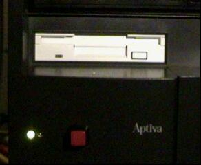
A closer look at the lights and power
button. The power light is at the left. Hard drive light (not lit
here) is at the right. |
| The photo below is of a different 2159
system. The owner (Bill) followed the instructions outlined above,
forgoing the optional LEDs. |
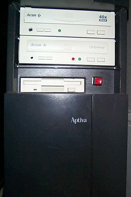 |
| Note that Bill later reversed the
procedure as he ended up giving his 2159 Aptiva to his mother upon
upgrading to a new 500 Mhz system. The only noticable after-effect
of this upgrade is a hole where the power button used to be, which
he has since covered up with an
insert. |
© 1998/1999/2000
Doug aka CoolAptiva
Reprinted with the permission of the
author
This document supplied free as a service
of
DON5408's Unofficial Aptiva Support
Site
http://members.aol.com/don5408/aptiva.html |
|
This document
is provided AS IS totally on an AT YOUR OWN RISK basis and neither
the author nor
the publisher provide any warranty or accept any
responsibility for any damage to anyone's PC due to the use or
misuse of any information provided
therein. | |